Quantcast
Channel: THE INVENTABLES WORKSHOP
Viewing all 247 articles
Browse latest View live

Easel Development Update

$
0
0
Hi, I'm Paul Kaplan, software engineer on the Easel team here at Inventables. The dev team has been thrilled to see the excitement about Easel, and we wanted to let everyone know how we'll be rolling it out to more users. We wanted to elaborate on our motivation for building Easel, and explain the next steps towards expanding access to everyone.

Here at Inventables we’ve been hard at work on Easel, a web-based app for CNC machines like the Shapeoko 2. Our goal with Easel is to make it fast, easy, and fun for anyone to go from having an idea to making a finished product.

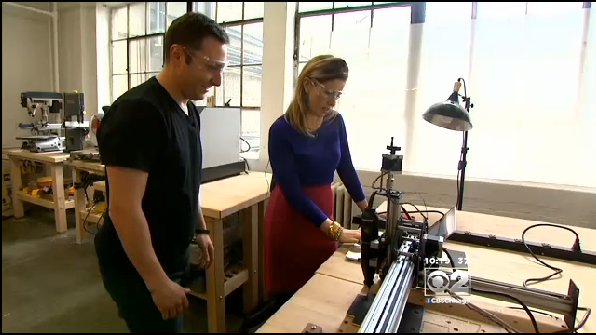
Our team recently went down to South by Southwest Interactive, where over 400 people had the opportunity to make custom bottle openers using Easel and the Shapeoko 2. Our CEO Zach officially announced Easel and was even joined onstage by Chicago mayor Rahm Emanuel. We take some pride in the fact that Easel is so easy even the mayor can use it! From a developers point of view, more important than seeing the mayor use our software was seeing young children also able to use Easel throughout the weekend.


IMG_1536 copy.jpg
One of our youngest Easel users yet at SxSW

What is it?
Easel is a browser based app to design and create projects on your Shapeoko. Instead of a complicated workflow with multiple pieces of software, Easel takes care of everything with one app. And it's totally free.

Why are we making Easel?
We believe that the distinction between artist and engineer is a false dichotomy. Here at Inventables, nobody is just one thing: we are programmers, makers, artists, and designers, often all at the same time. Software should give people the tools they need to cross those boundaries. An in-depth knowledge of technical settings should not be a prerequisite to designing a wooden sign, nor should a lack of design training stand in the way of making a cool product.

When can I use it?
Right now we are looking for Chicago area Shapeoko owners in order to learn the most from our beta testers. We hope to be able to release Easel to everybody on the early signup list by early summer.

We are looking for people who: 
live in the Chicago area
own a Shapeoko
are willing to meet with our developers in person to give feedback.

If that describes you, drop us a line at easel@inventables.com and join our beta test. 

As we continue to build out Easel, we’ll be able to roll out access to more and more users over the coming months. You can sign up for the waiting list at easel.com

We are so excited about making it easier than ever to use your Shapeoko. We are working furiously towards opening Easel to everyone on the signup list by the summer. We will try to provide weekly updates from the dev team on what we are working on.


Some of our team at SxSW
P.S. We’re hiring! If you’re a software engineer and want to help us build the future of digital fabrication, take a look at our careers page.

The Inventables team, all in one place!

$
0
0
We had a rare occurrence this week of nearly every single Inventables employee being in the Chicago office at the same time. (Sorry Joanne, we'll have to photoshop you in!)

Here's a group photo we took to document this astronomical event:


Greetings from everyone!

Kate Sullivan of CBS News features Inventables on the "Your Chicago" Segment

$
0
0
Kate Sullivan is co-anchor of CBS 2 Chicago News at 5 p.m. and 10 p.m. with Rob Johnson. Kate, who has won several awards – including an Emmy Award and the Associated Press First Place Award for Breaking News – joined us at Inventables for a tour, interview, and a little bit of making.

Kate Sullivan

Kate does a recurring segment for CBS called "Your Chicago".  Every Friday at 10pm Kate or her co-host Rob Johnson get out of the studio and explore Chicago.  Last week she came over to Inventables.  Kate was interested in learning more about our new free software called Easel and the Shapeoko 2.  She rolled up her sleeves and became a maker in minutes!  


We even got her into a pair of safety glasses!


Watch the full segment on the CBS News website.

Makerbot Replicator 5th Generation

$
0
0
We just got in some of the new Makerbot Replicator 5th Gens, and they're looking good!


Big improvements over the last model include:

  • Integrated camera so you can monitor/record your prints
  • Bigger, color LCD screen 
  • Wi-Fi connectivity
  • Updated Makerware software
  • Easier leveling
  • Glass build plate can slide out of the machine when your job is done
  • The new Smart Extruder system which allows
    • Magnetic mounting for easy replacement
    • Sensors to pause your job if it runs out of filament

The build volume is 7,522 cubic CM (456 cubic inches), about 11% larger than the Replicator 2. The print resolution is 100 microns/layer, and it's optimized for PLA filament.


We have a limited number of these highly sought machines in stock right now, so you might want to act quickly. After our initial supply is exhausted, we're looking at a ~6 week lead time.

Upgrading your Shapeoko 2 with NEMA 23 motors

$
0
0
A lot of people ask us about upgrading their Shapeoko 2 to use NEMA 23 motors on the X and Y axes. To make that process a little easier for everyone, we decided to offer up a project that includes all the components necessary, click here for the shopping list.


Important notes: 
  • This is an experimental modification
  • Your results may vary
  • You might do something weird and accidentally burn out your motor driver board
  • If that or something else catastrophic happens this is not our fault, you crazy hacker!

That said, here's the instructions. You crazy hacker you.

1. Head on over to the project page and order the list of parts. There's a convenient "add to cart" button that has everything you need.

1. Remove the motor carriage plates from your shapeoko. This basically means: disassemble your Shapeoko most of the way. You need to remove the motor carriages completely from the makerslide, and the easiest way to do this is to remove the screws that hold the makerslide to the plates and frame.

2. Remove the NEMA 17 motors and all the mounting hardware. You should now be left with something that looks like this:


3. Organize your mounting hardware for the NEMA 23s. Each one will need 4x button head cap screws, 4x spacers, 4x washers, and 4x hex nuts.

4. Mount the screw through the motor's mounting hole, then add a spacer, then pass it through the plate, then a washer and the hex nut and tighten it down. It's easier to get all 4 screws in and put the spacers on, then push them into the motor plate all at once. You might want to leave them a little loose until the later steps.


5. Repeat for the other motor mount plates.

6. Attach the pulleys to each motor shaft. You'll want to line each pulley up with the smooth idlers so the belt can travel in a straight line.


7. Once you've got all the motors mounted, you need to slide the motor carriages back onto the Makerslide and reassemble the machine. Here's where it gets tricky:

The NEMA 23's must be mounted on the bottom of their path of travel for the X-axis makerslide to be able to mount properly. Otherwise, the motor will get in the way and it won't work. it will be very frustrating.

Example:


Here's that same error from another angle:


If you move the NEMA 23 to the bottom of the mounting holes, it will look like this:


Once you do that, the Makerslide will drop into place easily and square up. So satisfying!


8. Once you get the mechanicals back together, reattach and thread your belts and tighten and calibrate everything. You're now free to experiment with this radical and unorthodox means of Shapeoko movement, including the highly dangerous process of adjusting the amperage on the Gshield motor controllers to give these 23's a little more oomph. 

Good luck, and you should probably check in on the Shapeoko forums to see how other folks have fared before you attempt this.

-Michael Una

You spin me right round baby!

$
0
0
We had a little fun with the new Knob with Crank for NEMA 17 and 23 stepper motors. For the record, you can use one stepper motor to generate enough power to turn another one, but the efficiency of that energy transfer is a little low...


If you want to turn this .gif into a dance party, here's your soundtrack- just hit play:


Hello World! Notes on using TinyG with Shapeoko

$
0
0
Alden Hart of synthetos, creator of the grblShield and tinyG motor controllers, took some time to write about using tinyG with Shapeoko. We followed his advice and hooked up one ourselves, and I have to say that we're really impressed by the difference- Shapeoko feels like a totally different animal with tinyG in charge.

Here's a video of tinyG controlling the machine to run a "hello world" job:


Here are the tgFX panels showing the correct settings for Shapeoko. Note that you may need to change the axis assignments and polarities for each motor depending on how you wired it up, which is one of the nice features about tgFX- just pay attention to your motor's coil pairs, and then do all the rest in the software.


And as a special treat, Alden's rundown of the setup, and explanation of the control principles. Thanks
Alden!

Shapeoko and TinyG

Shopeoko and TinyG are a great fit. The combination make a good upgrade to support very smooth, fast motor operation, built-in support for dual Y axis configurations, and other enhancements.

What Does It Do?

TinyG's motion control is very smooth due to precise timing and constant jerk acceleration. This means a number of things to the Shapeoko user. TinyG has an optimized, low jitter step generation coupled with constant jerk acceleration management. As a result TinyG gets a lot out of your motors. If you think you need to upgrade from NEMA17 motors to something larger you may find that more precise control offered by TinyG is really all you need.
The constant jerk acceleration management also makes for extremely fast rapids (traverses), which helps cut down job times. It does all this with minimal shaking of the machine and toolhead, making for smoother cuts, better surface finish, and less chance of skipping, chattering, or other artifacts.

Tgfx

TinyG works with tgfx, a cross-platform control program available for Mac, Windows and Linux. Tgfx provides a graphical user interface that lets you configure, run and monitor jobs.

Setup

Setting up Shapeoko to use TinyG is pretty straightforward. This page provides all the settings neededhttps://github.com/synthetos/TinyG/wiki/TinyG-Shapeoko-Setup
A few things to keep in mind.
  • TinyG treats motors independently from the axes. So it natively supports dual-y configurations. 2 motors map to the Y axis - and both are driven by Y axis controls. But they must be going in opposite directions (i.e. have reverse polarity settings) for the gantry to move as a unit. Polarity can be handled electrically by reversing one of the coil pairs on one of the motors, or under software control by setting the polarity motor parameter. I prefer firmware as this way all the motors are wired the same and are interchangeable.

Tuning Shapeoko and TinyG

Once you are set up you can tune the Shapeoko/TinyG system for optimal performance. There is a page on the TinyG wiki about tuning that the following was adapted from. What follows are tuning instructions and guidance specifically for the Shapeoko/TinyG combination.
Tuning the machine is about getting the maximum performance from the system while setting the "envelope" in which the machine can work. The envelope defines the reliable limits on all parameters. TinyG is written such that if Gcode asks for more than the machine can deliver (e.g. too high a feed rate) the system will execute the Gcode to the best of its ability while not exceeding the performance envelope. So it's important to tune the machine so you avoid over-specified Gcode files causing jobs to fail.

Mechanical

A well functioning mechanical system is the heart of tuning. The electrical system can at best compensate for the mechanical system, but can never fundamentally improve it. Here are a number of points to make sure the Shapeoko itself is tuned up.
  • Make sure the machine is in perfect alignment and belt tension is correct. All parts should be square and the belt axes (X and Y) should be tight but move with almost no resistance. Test that pulleys and wheels rotate freely and do not bind or wobble. Test that shaft couplers are well seated and tightened with minimum eccentric wobble ("runout").
  • It's a good idea to test slide resistance with no motors mounted. Look for any rough spots in the slide, or any points where resistance is greater than others. Test again once the motors are mounted. When motors are mounted make sure they are electrically disconnected from the stepper board, and their winding leads are not shorted (as this will cause mechanical resistance to go way up).
  • The Z axis should turn as smoothly as possible with no binding. Many people upgrade to an Acme screw for this reason. Observe similar guidance about mounting the motor.

Settings

Once the mechanical system is working well you can start in on the settings. Do these one axis at a time then in combination. All values are in millimeters using the X axis as an example. Other axes are similar.
Some terms:
  • The velocity maximum - aka traverse rate - is the top speed of an axis under no cutting load. Traverses (G0's) move the machine at the maximum velocity and generally don't change from job to job. A good maximum velocity will drive the motor reliably at high speed and allow for a little headroom where the motor is still running well. Attempting to set this rate above this speed may cause the motor to operate erratically, drop steps, or stall. These will be obvious if the motor makes grinding or other bad noises.
  • Bear in mind that with traverses (G0) the actual speed of movement may well be above any of the traverse rates of the individual axes as it's the cartesian sum. For example, if xvm and yvm are set to 10,000 mm/min a G0 from (0,0) to (100,100) will actually run at 14,142 mm/min (assuming it has room to accelerate to the target velocity).
  • The feed rate is the maximum cutting speed the axis can sustain for a given tooling, material and type of cut and may change considerably from job to job. The max feed rates set here are just an upper limit that a Gcode file cannot exceed. The actual control of feed rate should be done from the F words in the Gcode file itself. The max feed rates should generally be set lower than the maximum velocity.
  • The jerk is the rate of change of acceleration - technically the derivative of acceleration or the third derivative of position. In practical terms, jerk is a measure of the impact to the machine due to rapidly changing velocity. It causes the machine to - well - jerk. When setting jerk values you are looking for two things. (1) finding the minimum time the axis can get up to speed without stalling or missing steps (which you will be able to hear), and (2) finding the maximum jerk the machine can withstand along that axis without shaking too much. These might be different. Optimize for (2) over (1).

Axis Tuning

Axis tuning starts with getting good values for the following:
  • Velocity Maximum ($xvm)
  • Feed Rate Maximum ($xfr)
  • Jerk Maximum ($xjm)
  • Motor Currents (potentiometer settings)
CAVEAT: Be sure your machine is in mm distance mode before starting. 
The distance mode should be obvious from the command prompt:
tinyg [mm] ok> not:
tinyg [inch] ok>

Enter G21 to change to mm mode (G20 to change to inches)
Steps
Do these steps for each axis in turn.
  1. Ensure the Motor settings for step angle ($1sa), travel per revolution ($1tr), microsteps ($1mi), and polarity ($1po) are correct for each motor. Verify that the Axis settings for velocity maximum ($xvm) and jerk maximum $(xjm) are set correctly. If in doubt, go back to theTinyG Shapeoko Setup page
  2. Locate the X axis current setting potentiometer on the TinyG board and start with it at the middle position - 12:00. Never force the potentiometer or exceed the potentiometers' range of motion, which is 270 degrees, or from about 8:00 to about 4:00.
  3. Test a traverse with a long G0 move, such as G0 X100 (Be sure you have 100 mm of clearance on the X axis before you do this!) The motor should accelerate, cruise at speed, then decelerate to a stop - all in less than 1 second. The motor should not stall or fail to start. Lower the velocity in increments of 1000 mm/min if this is the case. You may also need to back off the jerk max - try increments of 1 billion (e.g. 5000 --> 4000).
  4. If the motor hums but doesn't start it's probably not getting enough current. Turn it up to 1:00 or 2:00. Alternately, if the motor stops and starts; or stutters; and the driver chips are excessively hot the motor is getting too much current. Turn the pot down a bit. Too much current will give just as bad results as too little. These drivers do not go to "11".
  5. If the the motor more or less works but seems to be dropping steps it could be any of the mechanical system (too much friction), the current setting, or the velocity max being too high; or possibly some combination of all three. Experimentation is required. It's best to try to fix them in that order. Start with the mechanical system, then the current, then the setting.
  6. Once you have the axis working you can see if raising the velocity ($xvm), the jerk ($xjm) and providing more current can increase the top speed. This is a case of experimenting. Try to avoid excessive current, however, as after a point the current setting provides diminishing benefits and only heats up the motors and risks thermal shutdown.
  7. Once you have the maximum velocity where you want it set the max feed rate to the max velocity value or somewhat lower. The max feed rates often require adjustment for a given job or material as the cutting loads may vary. The traverse rates should not require job-by-job adjustment.
It's worth noting that the mechanics of the axes may not be identical, and the achievable traverse rates may differ for each axis. You can set them optimally for each axis and moves in more than one dimension will takes the individual settings into account.
It's also worth noting that on some machines mechanical resistance is greater in some parts of the travel than others (e.g. more resistance at the ends of travel due to shaft coupler runout or other mechanical factors). Be sure to test the entire travel for each axis before finalizing the settings.

Tuning the Cornering Speeds

So far all the tuning has been about straight line movement. Cornering is is the rest of the story. Corner velocity is the maximum velocity the tool head can move through a corner without exceeding a setting to limit centripetal acceleration.
The centripetal acceleration limit is called Junction Acceleration ($ja) and can be found by looking at the system parameters by typing $sys. This value applies to all axes, as cornering is inherently a multi-axis movement.
Each axis is controlled by by its Junction Deviation value ($xjd). This sets how tight the "corner" is for that axis. The larger this number, the faster that axis can corner.
The settings provided in the Shapeoko setup are a good starting point. If you find the job is stalling or skipping in tight corners you will want to lower one or the other or both of these values.


Chicago North Side Maker Faire

$
0
0


The world-renowned Inventables street team was on hand at the Chicago North Side Mini Maker Faire today, and let me tell you, there was nothing mini about it!

We were introducing makers of all sizes to Easel—our free design software that runs right 
in your browser!


Easel allows you to design something in 2D, instantly view it in 3D, and cut it out of real materials like wood, plastic and soft metals on your Shapeoko.


Attendees made their own custom-designed keychains, and Easel took care of all the confusing technical details so they could focus on inspiration. 

Sign up for beta access at easel.com


 Also, there were adorable bunnies.


We are donating a 3D Carving Machine to Every State in the US!

$
0
0
San Mateo, CA – May 12, 2014Inventables, Inc. today announced it will give away 50 3D carving machines to publicly-accessible spaces in each of the United States. The announcement was made at MakerCon, a conference and workshop focused on digital manufacturing and hardware development that takes place in Silicon Valley. Organizers of maker spaces can apply here.

The Inventables team was inspired by the success of the Harold Washington Library in Chicago, whose Innovation Lab of 3D carvers, laser cutters, and 3D printers is free and open to the public.

“We believe that to ignite the digital manufacturing revolution, we need to provide free access to these important 3D carving tools to as many people as possible,” said Inventables CEO Zach Kaplan. “We hope that access to a free 3D carving machine and free software will help reboot American manufacturing education, and allow people to start their own small-scale manufacturing businesses in the United States.”

3D carving, also known as a CNC milling, is a powerful technology capable of creating precision parts and designs from materials like wood and metal. Unlike consumer-grade 3D printers, which can only use strands of plastic to create objects, 3D carving enables users to physically make a product or project on a computer controlled (CNC) milling machine using real materials. The 3D carving machines work with Inventables’ free software Easel to enable users to go from idea to design to running the machine in five minutes without any specialized knowledge or training.

Inventables is providing the Shapeoko 2, an open source, low­-cost desktop 3D Carver known by the technical community as a computer numerical control (CNC) mill, to 50 publicly-accessible locations. Libraries and hackerspaces interested in receiving one of the free 3D carving machines should apply at inventables.com/3dcarver

MAP OF EARLY CONFIRMED LOCATIONS
Screen Shot 2014-05-09 at 10.47.55 AM.png

In addition to libraries, Inventables is partnering with “Hackerspaces” across the United States, which are community gathering places where people with an interest in learning and technology can gather to work on projects while sharing ideas, equipment, and knowledge.

In Austin, Texas, Inventables is partnering with ATX Hackerspace. ATX Hackerspace has recently added a Startup Incubator program, where members can rent office space to turn the ideas they’ve been building into small business.

ATX Hackerspace Founder Martin Bogomolni:“The rise of these types of community hackerspaces is unprecedented in history. Our members openly share their knowledge and expertise on a whole host of subjects and some of those ideas are being turned into viable small businesses in emerging technology fields. It’s a very exciting time to have ideas and make real things.”

About Inventables

Founded in 2002, Inventables’ mission is to ignite the digital manufacturing revolution by simplifying the path from idea to finished product. Recognized as the hardware store for designers, Inventables sells desktop manufacturing machines and thousands of materials in small quantities. Small manufacturing businesses purchase raw materials and machines from Inventables’ online store daily to use in manufacturing their own products from jewelry to eyeglasses to sell to customers. When a material from the site is needed in a large volume, Inventables assists in making connections to the manufacturer or supplier.

inventables.com

About MakerCon

MakerCon connects individuals at the forefront of the maker movement in a two-day conference and workshop, from experts in digital manufacturing, to technology and tools providers, to accelerators that facilitate taking a prototype to market, and a broad swath of makers. The event will kick off with a number of three-hour workshops Tuesday morning followed by our stellar speaker lineup.

makercon.com

The DC Spindles Have Arrived!

$
0
0


We have been using these DC spindles internally for quite a while.  We absolutely love them and everyone who sees and/or hears them, loves them too.  The first thing to love is the sound level.  They are very, very quiet.  In a slightly noisy office, workshop or hackerspace you may not even know that it is on.

The second thing to love is the collet.  The collet is the part of the spindle that clamps the bit.  The collet is a standard ER11-A.  It comes with a collet for 1/8" shank bits, but we also sell collets for 3/16" and 1/4" shank bits.  We sell additional collet nuts too in case you want to pair your collets with nuts to save time when swapping sizes.


The third thing to love is the power.  These have over twice the power of a rotary tool.

Usage


We have an awesome and totally comprehensive blog post about using this spindle on a Shapeoko with spindle control via grbl or TinyG in the works.  It should be done shortly after Maker Faire.  In the mean time, this quick blog post will go over the basics.

Mounting.

The standard Shapeoko Universal Motor Mounts work very well to mount this spindle, but tends to mount it a little high.  It is easy to modify the Z axis to make it work.  You can either slide the Z axis MakerSlide down a little or swap the positions of the Z axis lead screw nut and upper mounting bracket to bring the spindle down a little.


We also sell a beefy standard mounting bracket, but these don't have a mounting pattern for a Shapeoko.


We have a custom Shapeoko mounting solution in process, but that won't be available for several weeks.

Powering.

As the name implies, this is a DC powered device.  You can power them with 24-48 Volts DC.  For best performance you want to be closer to 48VDC.  These draw up to 300 Watts which is probably more than you current power supply can deliver.  We recommend an a power supply with at least 6 amps, like this one.


Speed Control.


The top speed is about 12,000 RPM.  The speed can be controlled by varying the voltage or with a dedicated speed control circuit.  We sell this circuit. It comes with a knob and pot to control the speed, but it also can accept a 5V PWM signal to control the speed.


This circuit can accept DC or AC up to 110 Volts.  Using AC is for advanced hackers only.  It exposes dangerous voltages and the range of the control must be limited to the lower end because it will output too much voltage for the spindle.  You could damage the spindle or speed controller.

Circuit

A typical circuit would look like this.


Here are some more instructions.

How Quiet is It?

We don't have professional sound level measuring tools or an anechoic chamber, but for a simple comparison, I used a cell phone sound pressure level meter app.  The rotary tool had about 75dB of noise and the DC spindle had about 67dB of noise.  The dB scale is a logarithmic scale so each 3dB is about twice the noise level.  This means the rotary tool is roughly 7-8 times louder.

Here is a photo of the app measuring the rotary tool.


Impact Engine - June 22nd Deadline

$
0
0


Chicago-based accelerator Impact Engine is looking for passionate entrepreneurs trying to solve the world's toughest societal and environmental challenges. Its 16-week program is designed to provide mission-focused entrepreneurs with the capital, business resources, and network they need to build successful companies that positively impact the world. Apply by June 22nd for the opportunity to build and grow a successful impact business alongside like-minded entrepreneurs, mentors, and investors. 

If accepted, startups receive the following in exchange for 7 percent equity in the company: $25,000 in seed funding; access to dedicated mentors; business workshops and seminars; the opportunity to present at Demo Day; co-working space; pro-bono legal services; fundraising support; and more. Learn more at TheImpactEngine.com/Program or apply at TheImpactEngine.com/Apply. Applications will be reviewed on a rolling basis, so get yours in today!
Target Sectors: Climate & Environment, Education, Financial Services, Food & Agriculture, Health & Wellness, and Workforce Development
Inventables is donating access to our shop to any team accepted.  This means you can use your 3D printers, Laser Cutter, or 3D Carving machines known by the technical community as CNC Milling machines free of charge during your Impact Engine Experience.

Why the Maker Movement Is Important to America’s Future

$
0
0
Tim Bajarin
Tim Bajarin
I met Tim Bajarin at TED 2014 in Vancouver.  We started chatting and I asked "what brings to you TED"?  He explained since 1981 he has served as a consultant to most of the leading hardware and software vendors in the industry including IBM, Apple, Xerox, Hewlett Packard/Compaq, Dell, AT&T, Microsoft, Polaroid, Lotus, Epson, Toshiba and numerous others. He had met and worked with Steve Jobs on a number of occasions and also wrote articles for USA Today, Wall Street Journal, The New York Times, Time and Newsweek magazines, BusinessWeek and most of the leading business and trade publications. The TED Conference is a unique place where when you turn and chat with the unassuming person sitting next to you they often have a decorated history and are at the top of their profession.  In this case I was chatting with a person that had a front seat to the personal computer revolution.

We met up again last weekend at Maker Faire in San Mateo California.  Tim was walking around observing and interviewing people for an article he wrote in TIME titled "Why the Maker Movement Is Important to America’s Future".  There have been quite a few articles on 3D Printing and 3D Carving in the last few years.  The hype level on 3D is reached all time highs.  What struck me about Tim's article was the seasoned macro economic perspective that he brought to the details he observed.  The article is a compelling tale told only by someone who was there the first time and can bring that context and experience from the personal computer revolution.

I encourage everyone to read the entire article but if you only have a few seconds read this:

"As someone who has seen firsthand what can happen if the right tools, inspiration and opportunity are available to people, I see the Maker Movement and these types of Maker Faires as being important for fostering innovation. The result is that more and more people create products instead of only consuming them, and it’s my view that moving people from being only consumers to creators is critical to America’s future. At the very least, some of these folks will discover life long hobbies, but many of them could eventually use their tools and creativity to start businesses. And it would not surprise me if the next major inventor or tech leader was a product of the Maker Movement."

Ninjaflex Filament

$
0
0


We just got Ninjaflex filament in the store and are having a ton of fun with it.  It is super squishy and perfect for making car tires, bumpers and cell phone cases.  We wanted to print a ninja, so we used the official mascot of Pumping Station One's CNC Build Club: The CNC Ninja Squirrel.


We printed a few of them at about 40mm tall.


Next came the fun part.  We tried to torture them to death.  We could not kill them.  Ninjaflex is pretty cool stuff.


Print Settings.


We printed it using our MakerBot Replicator 2X.  The default lines came out rather thin so we created a custom profile for it.  That profile is attached below.  Unzip the file into the [username]/My Things/Profiles folder and you're good to go!


You select the profile from the dialog "Make" box.


MakerCon Recap: There's a revolution going on

$
0
0
Inventables' Zach Kaplan and Michael Una were out in the Bay Area recently for MakerCon, a conference "providing new insights into local and global manufacturing, design, workforce development, education and even creative culture", organized by the fine folks at Make Magazine. 

We learned a lot and had the opportunity to share some of our own experiences, and also got to make one big announcement.

In case you missed it, Zach gave a talk in which he announced that we're giving away a Shapeoko 3D Carving Machine to a public maker space in all 50 states (plus Washington DC and Puerto Rico).


If you're interested in applying, or know someone who might be, the application form and all the pertinent information is available here.

Zach gave a brief talk as part of a panel with Bunnie Huang and others on the process of going from idea to a finished product. He discussed some of the issues we've encountered as Shapeoko has grown and walked the audience through some of the processes we use to keep ourselves organized and efficient.


We saw a few great talks, most notable Kevin Kelly of Wired Magazine and Cool Tools fame, who discussed the history and evolution of the Maker Movement and where he sees it going. One quote that stuck with us:

"Tools underpin revolutions that occur in culture"


We were also impressed by Jay Silver of MaKey MaKey who gave an audiovisual tour-de-force that asked the question "What does it mean to be an undomesticated human?" This guys knows what's up. He has a lot of radical ideas about how humans learn, what it takes to be creative and happy, and how to retain childlike curiosity every step of that journey. He also advanced his powerpoint presentation by squishing his finger into a piece of fruit. He then set his computer to automatically take a picture when he and Dale Dougherty high-fived. Really inspiring stuff.


We also got to see a talk by our friend and awesome guy Massimo Banzi, who revealed some of the new plans for the next Arduino boards. A big focus for the Arduino team is making the user interface design as simple as possible, and to optimize for people who've never worked with electronics or programming before.

He told a pretty funny story about getting into a cab in Spain, and the driver kept staring at him in the rearview mirror. He then pulled over and whipped out his copy of "Getting Started with Arduino" and showed Massimo a video of himself that he had just been watching on his phone, waiting for a fare to get in. The cab driver was working on a hardware startup company and was just learning how to use Arduino. 


Overall, we loved getting to meet so many of the movers and shakers of the Maker movement in person and got a very good sense of the issues facing the maker community, as well as the prevailing ideas and trends that are going to shape the world for the next little while. It's an exciting time to be part of this burgeoning movement!

-Michael Una

So Many Hackerspaces!

$
0
0
While we were in the San Francisco Bay Area for MakerCon and Maker Faire, we decided to spend our evenings visiting as many local Maker/Hackerspaces as we could. I personally found it really interesting to see all the activity going on in the area, and each space had it's own character and mission that reflected its members and their approaches to making. It's a big wide world out there.

Day 1: TechShop SF

Techshop is a bit different than other maker spaces. It's a for-profit organization, kind of like a fitness gym but with waterjet cutters, welding equipment, and big ol' lasers. We visited the San Francisco location and set up a Shapeoko on one of the big worktables upstairs. My first impression was that this space is huge, clean, and well-organized. There were maybe 60 people throughout the building elbow-deep into various projects. I wish we had gotten more time to take the full tour because their machine shop downstairs looked amazing.


People crowded around and chatted about making while we walked them through making their own custom bottle openers with Easel & Shapeoko. For whatever reason, the "mushroom" icon was really popular everywhere we went in SF.

image courtesy Twitter user @techliminalhttps://twitter.com/techliminal

A few tweets from folks who were there:


Shapeoko and Easel image by Instagram user jacquelynvk
Image by Instagram user jacquelynvk


This awesome mechanical contraption was sitting in their front lobby. I couldn't resist.


Hackerspace tour part 2: Double Union

$
0
0
5/14/2014: Day two of our Bay Area Hackerspace tour brought us to Double Union, a hacker/maker space for women in San Francisco's Mission District. Their mission is to "create a community workshop where women can work on projects in a comfortable, welcoming environment." You can read a great article written by founding member Liz Henry on why they do what they do and how to make your own Feminist hackerspace here


This hackerspace was my personal favorite of the tour. The community had obviously take great care in setting up and organizing their space, and it felt very warm and inviting. The work spaces were laid out very well and there were separate areas for quiet working or studying and large-scale making. Hackerspaces can take on a lot of different forms, and this one was obviously a very tight-knit community that was proud of their space and supportive of their members in a very personal way.


Zach and I got the machine set up and gave a quick crash course on how to use a 3D Carving machine, strategies for design, maintenance of the machine, and an intro to Easel. Everyone had a lot of questions, but they took a lot of notes and I felt that all the questions were directed at getting the most out of the machine and keeping it maintained and functioning well.


Everyone (I think) got a chance to get hands-on with the machine and Easel and while the machine was chugging away on everyone's projects, we got to talk to the awesome members and hear about what they do and make. I was seriously impressed with the level of technical skill in the room, and even though many of them had not used this type of machine before they drilled down to the tiniest details very quickly. Definitely a sharper, more focused crowd than the average smattering of knowledge-seekers at a hackerspace, and that's saying a lot. I won't name names, but one member was so modest she only casually mentioned that she does animation for Lucasfilm and has had her work in several major motion pictures. No biggie.

We're all really excited to see what this crowd ends up making on the Shapeoko!


Learn about Milling: The "Inside Corner" Problem

$
0
0
Coming to a CNC mill from a laser cutter, it is easy to get tripped up by the physical size of the bit when making designs. Any time you want to cut out an inside angle, you need to keep in mind that you can't reach all the way into an inside angle with a rounded bit. This comes up frequently when making furniture or any type of joinery; this post was inspired by the awesome examples of CNC joinery from this Make magazine post. Let's dive into the problem with inside corners and illustrate strategies to fix it.


A rounded bit prevents reaching inside corners

The problem obviously depends on the size of your bit (let's call the bit radius R). An easy way to reduce the impact of this problem without modifying your design is to simply use a smaller bit. A laser cutter suffers from this only slightly because the 'bit size' is a tiny beam of light!

Fixing the inside corner problem

You can modify your design to compensate for this problem. There are actually several ways to cover the red area shown above. 

If you have VCarve Pro, there is a tool that will do these operations automatically. Skip to the end to see how to use it.

The dog-bone

One way is to round the corner and slide it out until the entire red area is covered. It is difficult to explain with words and much clearer in diagram form!


To do this in a vector graphics program, you make a circle with the radius of your bit centered at the corner, translate it by the values in the diagram X = Y = sqrt(R^2 / 2) and do a boolean union operation with the inside corner. This method lets the part sliding into this corner just barely 'kiss' the inside of the circle, which is good for joints that take stress because the corner is still supportive. Here is what the tool path and resulting joint will look like:


The T-bone


There is another way to cover that red area, though. Instead of 'pushing' a circle into the corner of your design, you can push a circle directly in one direction, up or sideways (diagram shows up). The math for this method is simpler: you only need to push a circle up by one radius from the corner. 


To work this into your design, use a boolean difference of this circle and the corner. The tool paths and resulting joint:


This method is biased in one direction, which can have a few effects:

  • If your design has another piece laying on top of the joint, the circular deviation can be completely covered up.
  • The corner is supported in one direction but not the other. Make sure if you want this joint to take load, plan out carefully which direction needs to be supported. If both have to be supported, you might want to use the first method
There are two ways you can fix the inside corner problem on a CNC. Few CAD programs do this automatically, but it is not hard to fix in a vector editor like Illustrator or Inkscape.

Do it automatically!

VCarve Pro has a really great built in tool for doing this automatically. From the Drawing menu, select the Create Fillets menu item (highlighted in the image below).


Enter your tool diameter and choose which technique you want to use.


To use the tool, simply click on an inside corner of your design. It will automatically insert the fillet in the correct position.

Warning: the fillet tool is not parametric; scaling your design after inserting fillets will scale the fillets as well. It is best to insert the fillets after the design is complete.


50 States Contest Winners Announced!

$
0
0
Inventables Announces Winners of Contest For Public Maker Spaces
to Win a 3D Carving Machine in Every State in the US

Chicago, IL, June 2, 2014 - Inventables wants every person in the United States to have access to the newest digital manufacturing technology, 3D Carving. To that end, they announced a pilot project on May 12, 2014 to give away one of their Shapeoko 3D Carving machines to a publicly-accessible space in each of the 50 United States.

“We believe that to ignite the digital manufacturing revolution, we need to provide free access to these important 3D carving tools to as many people as possible.”

The donated machines will be shipped to the winning organizations starting the week of June 16, 2014 and will be set up and ready for public use by mid-July.

3D carving, also known in industry as CNC milling, is a powerful technology capable of creating precision parts and designs from real materials like wood and metal, unlike consumer-grade 3D printers which can only use strands of plastic to create objects.

The machines work with Inventables’ free software Easel to allow anyone to go from idea to making in five minutes without any specialized knowledge or training. Inventables hopes that access to a free machine and free software will help reboot American manufacturing education, and allow people to start their own small-scale manufacturing businesses in the United States.

In addition to libraries, Inventables is partnering with “Hackerspaces” across the united states, which are community gathering places where people with an interest in learning and technology can gather to work on projects while sharing ideas, equipment, and knowledge.

One such Hackerspace that Inventables has partnered with is ATX Hackerspace in Austin, TX. Founded in 2009, ATX Hackerspace has recently added a Startup Incubator program, where members can rent office space to turn the ideas they’ve been building into small business. There are 12+ small business that have started within the space over the last year since the program was started.

ATX Hackerspace Founder Martin Bogomolni:“Our members openly share their knowledge and expertise on a whole host of subjects and some of those ideas are being turned into viable small businesses in emerging technology fields. It’s a very exciting time to have ideas and make real things.”

Small businesses that manufacture physical products are a quickly growing sector of the American economy. The Internet of Things and the larger umbrella of Digital Manufacturing are being driven forward by low-cost digital manufacturing tools being more widely available to the general public.

ATX Hackerspace Founder Martin Bogomolni: “At least a dozen small businesses have come out the hackerspace and at least two successful Kickstarter campaigns as well. We’re moving away from an era of mass manufacturing into a time of individual customization and small manufacturing, and hackerspaces are a breeding ground for that kind of innovation.”

Inventables CEO Zach Kaplan:“The majority of net new jobs come from startups and small businesses. These 3D carving machines present the opportunity for America to get back into manufacturing with a business model that makes sense in the new economy.”

Map of all applicants:


List of winners: (contact information for each space is available upon request)


State
Name
Website
Alabama
Mobile Makerspace
Alaska
Anchorage Makerspace
Arizona
Heat Sync Labs
Arkansas
The Launch Pad
California
Ace Monster Toys
Colorado
denhac
Connecticut
No response

Delaware
D Studio
Florida
Tampa Hackerspace
Georgia
7Hills Makerspace
Hawaii
Maui Makers
Idaho
East Bonner Public Library
Illinois
LevelUP Youth Makerspace
Indiana
The MakerHive
Iowa
The S.T.E.A.M. Room Fab Lab
Kansas
Johnson County Library Makerspace
Kentucky
LVL 1 Hackerspace
Louisiana
East Baton Rouge Public Library
Maine
Maine Fablab
Maryland
Baltimore Foundery
Massachusetts
P.irateship
Michigan
OmniCorp
Minnesota
The Hack Factory
Mississippi
No response

Missouri
Science City at Union Station
Montana
Bozeman Makerspace
Nebraska
Omaha Maker Group
Nevada
Bridgewire
New Hampshire
MakeIt Labs
New Jersey
FUBAR Labs
New Mexico
Quelab
New York
Staten Island Makerspace
North Carolina
Splatspace
North Dakota
MELD Workshop
Ohio
HIVE13
Oklahoma
Tulsa City Librarium
Oregon
ADX
Pennsylvania
Academy at Palumbo
Rhode Island
Cranston Public Library
South Carolina
MakeLab Charleston
South Dakota
GnomeShop
Tennessee
MidSouth Makers
Texas
10bit Works
Utah
Cache Makers
Vermont
Burlington Generator
Virginia
757 Makerspace
Washington
OlyMega
West Virginia
No Response

Wisconsin
Appleton Makerspace
Wyoming
Powell Middle School


About Inventables
Founded  in  2002,  Inventables’  mission  is  to  ignite  the  digital  manufacturing  revolution  by simplifying  the  path  from  idea  to  finished  product.  Recognized  as  the  hardware  store  for designers,  Inventables  sells  desktop  manufacturing  machines  and  thousands  of  materials  in small quantities. Small manufacturing businesses purchase raw materials and machines from Inventables’  online  store  daily  to  use  in  manufacturing  their  own  products  from  jewelry  to eyeglasses  to sell to customers. When a  material from the site is needed in a large  volume, Inventables assists in making connections to the manufacturer or supplier.

inventables.com

###
Note  to  editors:  High ­resolution  images  are  located  in  the  Inventables  Press  Kit  at
www.inventables.com/press

Shapeoko Upgrade - Quiet Cut Spindle with gShield and Relay

$
0
0
One of the best upgrades for the Shapeoko is to use a spindle instead of the rotary tool that many start with. The 300 Watt Quiet Cut Spindle from Inventables works great with the Shapeoko desktop CNC. It is a great upgrade for many other DIY CNC router designs as well.

To make your life a little easier, we've compiled all the parts necessary for this upgrade into a single project that can be purchased here.


The Quiet Cut Spindle has several features that make it perfect for this application.
  • very quiet, compared to the rotary tool, you barely hear it running
  • great tool holding, with a industry standard ER11-A collet included
  • additional collets available
  • air cooled
  • compact and light weight
  • affordable

Hooking it up to work with the gShield (previously known as grblShield) on the Shapeoko is a pretty simple procedure that only requires a few more items, and most people should be able to perform the upgrade in a few hours. When the gShield is hooked up correctly the spindle will turn on and off with G-code directly with software. To make this happen the Arduino sends a signal as 5VDC though pin D12 to a relay. Although the gShield and Arduino combination can signal the spindle stop and start commands, it would damage them to run the 48 volts for the spindle directly. By using the relay we separate the voltages from the controller and the power supply. Think of the relay like a remote controlled switch. With a more sophisticated controller like the tinyG the relay is not needed and also the speed can be controlled as well with software. A tinyG and Quiet Cut Spindle blog post is in the works.

Additional items:
Parts needed for this upgrade to the Shapeoko

Tools needed:
  • soldering iron & solder
  • wire stripper
  • wire cutter
  • screwdrivers
  • multimeter for testing, optional

Final wiring for all components in this upgrade.


Video Tutorial:


Illustrated Directions:

Step 1) Extend spindle motor wires
Temporarily mount the Quiet Cut Spindle in the Shapeoko. Measure the 2-conductor wire needed to extend motor wires to where the 48VDC power supply and relay will be located. Measure twice, cut once. Extend motor wires by soldering on new wires and covering with heatshrink tubing or by using crimp connectors. Soldering and heat shrink is the preferred method.

Step 2) Wire relay to gShield
Add three pins to gShield used to connect to the relay circuit. You will need to connect to +5VDC, ground and digital pin D12 on the gShield. For this example I soldered on header pins to the gShield and then used female to female jumper wires, included with the relay. Feel free to use whatever technique you want for your application. In the photos and video I used red for +5VDC, green for ground and Yellow for signal (D12). See photos for wire locations.
gShield removed from Arduio to show where pins are located.
Arduino UNO board with arrows to show where to connect to relay.
I used header pins in this example to hook up wires to relay. I soldered these on to line up with the Arduino pins.
I used a "helping hand" tool to hold the glShield and rested the pins on a roll of tape to hold pins in place while I soldered.
Closeup of gShield with wires attached to relay board.
Wires from gShield to relay. Red is +5VDC, yellow is signal wire from D12, green is ground. Blue wire is unused.

Step 3) Wire 48VDC power supply
NOTE: check the input voltage on Power Supply. The default setting is 220V. Use a small screwdriver to slide the switch if needed. I cut the end off of a grounded power cable from Inventables. I stripped the wires to expose the ends and connected them to the power supply. They are color coded. For 110V in the USA green is earth, white is neutral and black is load. You can use a power strip for both power supplies so you can power the gShield and the spindle all at once.

Note power supply switch for input voltage. Make sure to switch to 110v if used in the USA.
Power in from outlet via power cord (shown on right) green is earth (ground), white is neutral, black is load. Please follow local standards in your country if different then the USA. 48VDC wires on left go to speed controller.

Step 4) Wire 48VDC power supply to speed controller
Use some more of the 2-conductor wire hook up the 48VDC output from the power supply to the input side of the speed controller. Note the speed controller can accept both AC and DC power so polarity does not matter on the input side of the speed controller. Also connect the negative wire from the spindle motor on the negative terminal on the output of the speed controller.

Speed controller has input on right side as shown and output on left side.

Closeup of jumper position on speed controller for use with gShield.

Step 5) Wire relay to speed controller
The relay circuit board has three contacts via a terminal block. We are going to use the NC (normally closed) pair. This means that if the relay is not powered the circuit is closed and power is being sent from the 48VDC power supply to the spindle. Once gShield, via the Arduino, triggers the relay via the D12 pin, the relay will energize and open the circuit making the spindle stop. Please see the photos or video for wire locations.

Wires on left connect to gShield, wires on right are the +48VDC wire from power supply and +48VDC to spindle. It does not matter which wire is connected where as long as they use the two right terminals (Normally Closed).

Step 6) Power up and test
Secure the spindle securely in the Shapeoko. Also remove the bit if you have one installed and make sure the collet is secure. Put on your eye protection. Using the potentiometer connected with the 3-conductor white wire to the speed controller move the dial to the middle position. Having both the 24VDC power supply for the gShield and the 48VDC power supply hooked up to the same power strip is an easy way to power both at once. Power on the system. You might hear the spindle start up momentarily until the grablShield initializes. Plug the gShield to your computer via USB and launch Universal-G-Code-Sender. Once you have connected to the machine you can test your connection by jogging the machine via one of the axis. If that works then type M03 (with a zero not an O) in the command line. to turn on the spindle. M05 should stop the spindle.

Note: the CAM program you are using is probably putting M3 or M5 in already near the beginning and end of the gcode. If not, it is usually an option somewhere or in the post processor. Also M3 and M03 are usually interpreted the same by the machine controller, so either will work. Same for M5 and M05. Please open up your G-code in a text editor or Universal Gcode Sender and preview before running your job.


Type directly in the command line to turn the spindle on and off M03 (on) and M05 (off). You can then add this directly to your G-code. If your spindle does not turn on check the potentiometer on the speed controller.
NOTE: there are no software changes that need to be made to make this work. The M03 and M05 commands are standard G-Code commands and are already included in the libraries.

Troubleshooting:
If you are not getting the spindle to power up check the following. Do you have a green light on the power supply? If not check the input voltage and wiring. You may need to power it down for 10 seconds or longer for it to reset. Check the lights on the relay circuit to see if they are being triggered by the Arduino and gShield. Also check the speed controller potentiometer. Set the dial to the middle position when testing. Once it is working well set it to full power unless you need to slow it down for the material you are cutting. If you need more help you can send an email to help@inventables.com.

Mounting of the Quiet cut spindle:
Due to the smaller size of the spindle you may have to change some mounts on your Shapeoko depending on the size of material you want to cut. We will cover some of these different mounting options in an upcoming blog post.


Milling 101: Understanding Milling Bits

$
0
0
Choosing the right milling bit for the job at hand can be an extremely important factor in whether a milling project comes out amazingly, alright, or not at all. Combine that with having more choices of bits than materials, and choosing the right bit can be quite a difficult task. However, by answering a simple set of questions, you can greatly simplify your choice of bit. Here are the things you need to ask:

  • What material am I cutting?
  • What is my machine capable of?
  • What shape am I cutting?


Let’s quickly go through each of these and what they mean.

What material am I cutting?


Your material is one of the most important single factors in choosing a bit. Materials have a lot of properties that matter both for your design and cutting (hardness, density, size) as well as just for cutting (how does it chip? melting point, thermal conductivity). For any combination of these properties, one thing remains constant: your bit must be sharp. A dull bit will always cut poorly, and can actually be dangerous to use due to increased likelihood of breakage. Most of the bits sold by Inventables are made of solid carbide, which is an excellent choice for small machines because of its stiffness, durability, and versatility.


Your material likely breaks down into one of three categories: plastics, woods, and metals.
Plastics are fairly soft and extremely versatile materials. They cut easily and tend to take a very smooth finish with no further processing. Plastics also form very nice chips off of the bit when they are being cut, which makes choosing your cut settings very predictable (but we’ll get to that later).


Wood is beautiful and strong, and although it cuts smoothly and quickly, it doesn't tend to be as smooth as most plastics. This is because wood has grain and fibers, which tend to tear and bend when you cut them, rather than cleanly shear. Wood also forms small chips and dust when cut rather than continuous curls like plastics tend to.


Metals (particularly softer metals like aluminum and brass) are the strongest, hardest, and most difficult to cut of the three groups. You can do amazing things with metals, but only if your machine can handle it. Speaking of your machine, that’s the next thing to think about.


What is my machine capable of?


Cutting any material puts a strain on your machine. For smaller machines like the Shapeoko, this often shows as the spindle twisting side-to-side, or the whole x-axis twisting front-to-back. Whenever your machine moves like that, you lose accuracy and unnecessarily wear your machine down. Cut settings and bit choice can minimize the force needed to cut a material, resulting in less strain on the machine. That being said, a stiffer machine will allow use of larger bits and higher speeds. The other thing to consider is how fast and accurate the spindle of the machine is. In general, for small machines, the higher the speed the spindle can reach, the better. It is also important to have the spindle be accurate, with very little wobble. When a bit is in the spindle, if it is not straight or wobbles (the spindle has runout), the bit will not cut evenly or accurately. Smaller bits can even break if the spindle is inaccurate enough.

What shape am I cutting?


Most jobs fall into two categories of geometry: 2.5D and 3D. 2.5D jobs have two-dimensional shapes that are cut to different depths. 3D jobs have complex, 3D surfaces. 3D machining requires a different bit shape than 2.5D machining. The other important thing with both 2.5D and 3D is what the size of the smallest detail is. In general, you want to choose the largest bit that can both cut your part and be safely used in your machine. A larger bit is stronger, and allows you to remove more material faster. However, larger bits can’t cut smaller corners or details, so you must consider the detail you need when choosing bit size.


So far we’ve been pretty general, so let’s dive into some specifics about the actual cutting bits.
This is a generic, 4-flute, square end mill. It’s one of the most common bits you can get. Let’s go over what that means. There are channels between each cutting edge called flutes. They act to carry away the chips from the cut. In this case, there are four of them, meaning there are also four cutting edges. The flutes spiral up towards the shank of the bit, so we call it an upcut bit. Finally, the edges of the bit all the way at the bottom are square, making it a square end bit. They could also be chamfered (bull end) or rounded (ball end). There are a few measurements on the bit itself that are important. There’s bit diameter (how big around the part that actually cuts is), shank diameter (how big the part that goes into the spindle is), bit length (how deep the bit can cut), and overall length (how long the whole bit is). Additionally, there’s the number of flutes (usually 1, 2, or 4) and the angle of the flutes (although we really only care if it’s up, down, or straight).


Now let’s focus on the cutting action. When the machine is running, the bit is spinning and being pushed into the material. Whenever one of the cutting edges comes into contact with the material, it cuts it away into a chip. The chip curls into the a flute of the bit, and is flung out from the cutting area to contribute to the mess around your machine.This is where the angle of the flutes comes into play. If you use a standard upcut bit, then as the bit cuts, it also pulls slightly up on the material. This is great for pulling chips out of deep, narrow cuts. However, on woods or laminates, that slight upward pull can cause a some chipping of the grain around the top edge of the cut as the grain is pulled upward instead of shaving cleanly off. A straight flute bit pulls material neither up nor down, and so behaves well on wood. Straight flute bits are especially great for plywood, as they reduce chipout on both the top and bottom surfaces. Downcut bits push material slightly downward, which is good for cutting thin laminates as it leaves the top surface very clean. However, chips can build up in the cut, affecting deeper cuts. This is somewhat true of all bits. If chips are not cleared from the cut, then when the bit comes back to the same location, it will be re-cutting those chips as well as the existing material. This shortens the life of the bit, makes cuts less accurate, and can reduce the quality of finish that your bit will leave on the material. Bit shape is one way to clear chips from a cut. Brushes, vacuums, and small blasts of air are also effective.
So with that being said, let’s look at some bits and when to use them.
25295-02

Two-Flute Square-End Mill

This is the workhorse bit. It’ll cut just about anything but the despair around a broken heart.
25295-01


Two-Flute Straight Cut End Mill


It’s awesome for cutting plywood because the flutes don't pull upward as they cut, which reduces chipping in the top layer.

25294-02


Two-Flute Ball End Mill

The end is round, which allows for fine detail to be cut on 3D surfaces. It will not, however, cut flat horizontal surfaces.

25295-03


Single-Flute Upcut End Mill


This is another upcut bit, but it only has one flute and the tip of the cutting edge resembles a hook. It cuts plastics and other really soft materials beautifully, and the hook tip helps cut through thin materials better.

30423-01


Fishtail End Mill


This is a slight variation on the standard square end mill, in that the tips of the cutting edges extend down past the center of the bit. It’s good for punching through thin material and getting fine detail.

26007-01


Engraving Bit


The tip is really tiny, only 0.01” in diameter! It’s tapered to make it stronger, which also has the effect of making the cutting diameter increase the deeper you cut. These bits are only for engraving very fine detail, but they’ll do it in any material.


With that selection of bits, you can mill just about anything that will fit on your CNC router. So make a choice, and go get your mill on!

Viewing all 247 articles
Browse latest View live